Ultrasonic Pulse Velocity (UPV) Test on Concrete
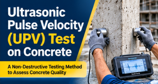
Concrete is one of the most important construction materials used in residential buildings, commercial structures, bridges, dams, industrial facilities and other infrastructure projects. The strength, durability and service life of any concrete structure depend on several factors, including material quality, mix proportions, placing, compaction and curing.
However, defects such as internal cracks, honeycombing, voids, segregation and poor compaction can develop during construction or throughout the service life of a structure. Identifying these defects is important for assessing the condition and durability of concrete.
Conventional destructive testing methods, such as concrete core testing, provide useful information about in-situ concrete strength but require the removal of concrete from the structural member. This may not always be desirable, especially when investigating existing buildings or important structural components.
To overcome this limitation, engineers use Non-Destructive Testing (NDT) methods to investigate the condition of concrete without causing significant damage.
One such method is the Ultrasonic Pulse Velocity (UPV) Test, which is performed in accordance with IS 516 (Part 5/Sec 1):2018 – Hardened Concrete: Methods of Test, Part 5 Non-Destructive Testing of Concrete, Section 1 Ultrasonic Pulse Velocity Testing.
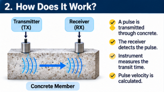
The UPV test measures the time taken by an ultrasonic pulse to travel through concrete over a known distance. Using the measured distance and transit time, the pulse velocity is calculated.
Generally, higher pulse velocity indicates better concrete uniformity and ultrasonic transmission characteristics, whereas lower velocity may indicate internal cracks, voids, honeycombing or other discontinuities.
The test is widely used for assessing concrete uniformity, identifying possible internal defects, comparing different structural members and investigating the condition of existing concrete structures.
In this article, we will explain the complete UPV test concrete procedure as per IS 516 (Part 5/Sec 1):2018, including its working principle, apparatus, transducer arrangements, formula, calculations, result interpretation, practical applications, limitations and an illustrative case study.
What Is the Working Principle of the Ultrasonic Pulse Velocity Test ?
The working principle of the Ultrasonic Pulse Velocity Test is based on the transmission of ultrasonic stress waves through concrete.An ultrasonic pulse is generated by an electroacoustical transducer. When this pulse enters the concrete, it undergoes multiple reflections at the boundaries of different material phases present within the concrete.
A complex system of stress waves develops, including:
- Longitudinal or compressional waves.
- Shear or transverse waves.
- Surface or Rayleigh waves.
The UPV machine measures the time taken by the pulse to travel between the transmitting and receiving transducers.
The velocity is then calculated by dividing the known distance between the transducers by the measured transit time.
How Does Concrete Quality Affect Pulse Velocity?
The pulse velocity depends mainly on the density and elastic properties of concrete. These properties are influenced by the materials and mix proportions, aggregate characteristics, placing, compaction and curing.
When concrete is dense and relatively uniform, ultrasonic pulses generally travel through it at higher velocities.
However, when a pulse encounters a crack, air void or internal discontinuity, its direct transmission is obstructed. The pulse may travel around the defect, increasing its effective travel path and transit time.
As a result, a lower apparent pulse velocity may be recorded.
It is important to understand that the UPV test indicates the condition of concrete along the ultrasonic transmission path. It does not directly measure compressive strength or provide a complete image of the internal structure.
Ultrasonic Pulse Velocity Test instrument and Apparatus Required
As per IS 516 (Part 5/Sec 1):2018, the apparatus used for ultrasonic pulse velocity measurement consists of the following components.Electrical Pulse Generator
The electrical pulse generator produces the electrical signal required to excite the transmitting transducer and generate an ultrasonic pulse.Transducers
A pair of electroacoustical transducers is used:- Transmitting transducer : Converts the electrical signal into an ultrasonic mechanical pulse.
- Receiving transducer : Detects the arriving ultrasonic pulse and converts it into an electrical signal.
The standard discusses frequencies ranging from 10 kHz to 200 kHz. Frequencies between 25 kHz and 100 kHz are useful for most applications.
Higher-frequency transducers are generally preferred for shorter path lengths, whereas lower-frequency transducers are suitable for longer path lengths because high-frequency pulses experience greater attenuation while travelling through concrete.
Standard Calibration Bars
Calibration bars are used to verify the performance and accuracy of the testing instrument.The standard specifies two reference specimens, usually steel bars, having known pulse transit times.
The equipment should be checked according to the calibration requirements of the standard and the manufacturer's instructions.
Amplifier
The amplifier increases the strength of the received electrical signal so that the timing device can detect the pulse accurately.Electronic Timing Device
The electronic timing device measures the time interval between the generation of the ultrasonic pulse and its arrival at the receiving transducer.The transit time is generally displayed in microseconds (µs).
Coupling Agent
A suitable coupling material is required to ensure proper acoustic contact between the transducers and concrete.Commonly used coupling agents include:
- Petroleum jelly.
- Grease.
- Liquid soap.
- Kaolin-glycerol paste.
Performance Requirements and Calibration of Ultrasonic Pulse Velocity Test Equipment
Before starting the test, the performance of the UPV instrument should be checked.IS 516 (Part 5/Sec 1):2018 specifies that the apparatus should be capable of measuring transit times with an accuracy of ±1% over a range of 20 microseconds to 10 milliseconds.
Two standard reference specimens are used for checking the instrument:
- The shorter reference specimen is used to set the zero of the apparatus.
- The longer reference specimen is used to verify the accuracy of transit-time measurement.
The measured transit time should not differ from the known reference value by more than ±0.5%.
It is also advisable to perform a zero-time check by applying a coupling agent to the transducers and pressing their faces together. This check should be repeated at suitable intervals.
Proper calibration is essential because even a small error in transit-time measurement can influence the calculated pulse velocity.
Another important precaution concerns long connecting cables. When leads longer than 20 m are used, they should not be allowed to come into close contact with each other because unwanted signal pickup may result in incorrect or unstable readings.
Ultrasonic Pulse Velocity Test Concrete Working Procedure stepwise
The UPV test concrete procedure should be performed systematically to obtain reliable and repeatable results.
The following steps explain the practical testing method.
Step 1: Selection of Test Locations
Identify the structural members and locations where concrete quality needs to be investigated.UPV testing can be performed on:
- RCC columns.
- RCC beams.
- Concrete slabs.
- Foundations.
- Retaining walls.
- Bridge components.
- Precast concrete members.
If visible cracks, honeycombing or suspected defects are present, additional test locations should be selected around the affected areas.
Step 2: Surface Preparation
- At each observation point, prepare the concrete surface properly.
- Remove plaster, paint, coatings and loose particles to expose the concrete.
- Carborundum stones or suitable grinders may be used to smooth rough surfaces.
- Care should be taken not to damage the concrete while preparing the test area.
- Proper surface preparation is essential for obtaining adequate contact between the transducer and concrete.
Step 3: Measurement of Test Path Length
Measure the distance between the transmitting and receiving transducers.This distance is known as the pulse path length.
The path length should be measured accurately because it is required for calculating pulse velocity.
The minimum recommended path lengths for direct transmission are:
- 100 mm for concrete having nominal maximum aggregate size of 20 mm or less.
- 150 mm for concrete having nominal maximum aggregate size between 20 mm and 40 mm.
For indirect transmission along an unmoulded surface, a minimum path length of 400 mm is recommended.
Step 4: Application of Coupling Agent
Apply a suitable coupling agent to the contact surfaces of both transducers.The purpose is to ensure good acoustic contact and minimise air gaps between the transducers and concrete.
Step 5: Positioning of Transducers
Place the transmitting and receiving transducers on the concrete according to the selected transmission arrangement.The three arrangements are:
- Direct transmission.
- Semi-direct transmission.
- Indirect or surface transmission.
Step 6: Taking Ultrasonic Measurements
Switch on the instrument and verify that it is functioning correctly.Hold the transducers firmly against the concrete surfaces.
The transmitting transducer generates an ultrasonic pulse, which travels through the concrete and is detected by the receiving transducer.
The machine displays the transit time in microseconds.
Record the transit time and corresponding test path length.
Step 7: Grid Marking and Multiple Observations
Concrete is a heterogeneous material, and its properties may vary from one location to another.Therefore, a single reading should not be considered sufficient for evaluating an entire structural member.
As per IS 516 (Part 5/Sec 1):2018, suitable grid markings of 300 × 300 mm or smaller may be adopted, with each intersection representing an observation point.
For general assessment of larger structures having uniform cross-sections and no visible distress, grid spacing up to 500 × 500 mm may be adopted.
The number of test points depends on the structure's dimensions, concrete variability and required accuracy.
Step 8: Calculation of Pulse Velocity
Calculate pulse velocity using the measured path length and transit time.Step 9: Interpretation and Reporting
Interpret the measured velocity according to the applicable quality grading criteria.Compare readings across the structural member and identify locations showing significant variations.
If doubtful results are obtained, further investigation should be carried out.
Types of Transducer Arrangements in the Ultrasonic Pulse Velocity Test
IS 516 (Part 5/Sec 1):2018 describes three arrangements for ultrasonic pulse velocity measurement.Direct Transmission or Cross Probing in the Ultrasonic Pulse Velocity Test
In direct transmission, the transmitting and receiving transducers are positioned on opposite faces of the concrete member.The transducers should preferably be placed directly opposite each other.
This arrangement provides the most efficient transmission of ultrasonic energy and is the preferred method whenever both opposite faces are accessible.
Advantages of Direct Transmission or Cross Probing
- More efficient ultrasonic transmission.
- Better signal strength.
- More reliable measurement of pulse velocity.
- Suitable for investigating internal concrete quality along the transmission path.
Applications: Columns, beams, walls and precast concrete members.
Semi-Direct Transmission in the Ultrasonic Pulse Velocity Test
In semi-direct transmission, the transmitting and receiving transducers are placed on adjacent surfaces or on opposite surfaces without being directly opposite each other.This arrangement is useful when the direct transmission arrangement cannot be adopted because of accessibility limitations.
The distance between the transducers should be measured along the actual straight-line path through the concrete.
Indirect or Surface Transmission in the Ultrasonic Pulse Velocity Test
In indirect transmission, both transducers are placed on the same concrete surface.This arrangement is used when only one surface of the structural member is accessible.
For example, it may be used for testing a concrete slab where the underside cannot be accessed.
However, indirect transmission is the least sensitive arrangement.
As per the standard, the signal amplitude obtained through indirect transmission may be only 2 to 3% of that obtained through cross probing.
The measured indirect velocity is generally lower than the direct velocity of the same concrete member.
The difference may vary depending on the concrete condition and other testing parameters.
For indirect transmission, Annex A of IS 516 (Part 5/Sec 1):2018 provides the procedure for determining pulse velocity using measurements taken at different transducer spacings.
The transmitter is kept at a fixed location, while the receiver is moved along a selected line at different distances.
The transit times are plotted against the corresponding distances. The slope of the best-fit straight line is used to determine the mean pulse velocity.
Important: Direct, semi-direct and indirect transmission readings should not be treated as directly interchangeable.
Ultrasonic Pulse Velocity Test Concrete Formula
The UPV test concrete formula is based on the relationship between distance, time and velocity.The formula specified in IS 516 (Part 5/Sec 1):2018 is:
V = L/T
Where:
V = Ultrasonic pulse velocity.
L = Distance travelled by the pulse.
T = Transit time.
When the distance is expressed in metres and time in seconds, velocity is obtained in metres per second (m/s).
When distance is expressed in millimetres and time in microseconds, the numerical value of velocity is obtained directly in kilometres per second (km/s).
Interpretation of Ultrasonic Pulse Velocity Test Results as per IS 516 (Part 5/Sec 1):2018
The interpretation of UPV test results is an important part of the investigation.The standard explains that pulse velocity is mainly related to the density and modulus of elasticity of concrete.
These properties are influenced by the materials, mix proportions, placing, compaction and curing.
Poor compaction, segregation, internal cracks and flaws may result in lower pulse velocity.
Excellent Concrete Quality Grading
When the measured velocity is above 4.50 km/s, the concrete falls within the Excellent category under the amended grading criteria.This indicates good ultrasonic transmission and generally favourable concrete uniformity.
Good Concrete Quality Grading
For concrete of grade M25 and below, velocities from 3.50 to 4.50 km/s fall within the Good category.For concrete above M25, velocities from 3.75 to 4.50 km/s fall within the Good category.
Doubtful Concrete Quality Grading
For concrete of grade M25 and below, velocity below 3.50 km/s is classified as Doubtful.For concrete above M25, velocity below 3.75 km/s is classified as Doubtful.
In such cases, additional tests should be performed to investigate the cause of the low reading.
Possible reasons include internal voids, poor compaction, segregation, cracks and other discontinuities.
Factors Affecting Ultrasonic Pulse Velocity Test Results
Several factors influence the measured pulse velocity. Engineers should consider these factors before interpreting the readings.Surface Condition and Moisture Content
Rough and uneven surfaces can affect acoustic contact between the transducer and concrete.Moisture content also influences pulse velocity.
As per Annex B of the standard, the pulse velocity of saturated concrete may be up to 5% higher than that of similar dry concrete.
Path Length and Size of Concrete Member
Concrete is heterogeneous, and the selected path length should be sufficient to minimise the influence of local material variations.The dimensions of the concrete member can also influence pulse propagation, particularly when the lateral dimensions are small in comparison with the wavelength.
Temperature of Concrete
Temperature influences ultrasonic pulse velocity.According to the standard:
- Between 5°C and 30°C, temperature variations do not significantly affect pulse velocity.
- Between 30°C and 60°C, pulse velocity may decrease by up to 5%.
- Below freezing temperature, freezing of free water may increase pulse velocity by up to 7.5%.
Stress in Concrete
When concrete is subjected to abnormally high stress, microcracks may develop and influence ultrasonic transmission.The effect becomes particularly relevant when stress levels are high enough to cause internal cracking.
Reinforcement
Steel transmits ultrasonic waves faster than concrete.The pulse velocity in steel is approximately 1.2 to 1.9 times the velocity in plain concrete.
Therefore, reinforcement near the pulse path may result in higher apparent velocity readings.
Contact Between Transducer and Concrete
Poor contact can affect the readings.A suitable coupling agent should be used, and the transducers should be pressed firmly against the prepared concrete surface.
Cracks and Voids
Air-filled cracks and voids obstruct ultrasonic transmission.The pulse may travel around the discontinuity, increasing the transit time.
However, small defects may not significantly influence the measure
Practical Applications of the Ultrasonic Pulse Velocity Test
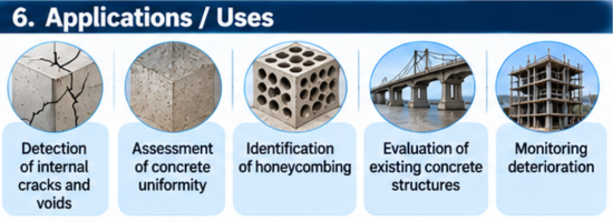
The ultrasonic pulse velocity test application covers several areas of construction and structural engineering.
Assessment of Concrete Uniformity
UPV testing is useful for comparing concrete quality across different locations within the same structural member.By conducting measurements at multiple grid points, engineers can identify variations in pulse velocity and investigate potentially weak areas.
Detection of Internal Cracks and Voids
The test can help identify possible internal cracks, voids and other discontinuities that obstruct ultrasonic transmission.It is particularly useful when visual inspection alone cannot provide sufficient information.
Assessment of Existing Buildings
UPV testing is widely used during structural condition assessments of existing buildings.It helps evaluate concrete uniformity in columns, beams, slabs and other RCC members without requiring extensive destructive investigation.
Quality Control During Construction
The test can be used as a supplementary quality-control technique to compare concrete uniformity in different structural members.It may help identify areas where compaction, placing or workmanship requires further investigation.
Assessment of Fire-Damaged Concrete
High-temperature exposure can alter the internal properties of concrete.UPV testing can help identify variations between fire-affected and relatively unaffected areas.
Further testing is necessary to determine the actual extent of damage and structural implications.
Evaluation of Repair and Rehabilitation Work
UPV measurements can be used to compare ultrasonic transmission characteristics before and after repair work.However, improvement in pulse velocity alone does not establish the structural effectiveness of the repair.
Testing of Bridges, Dams and Infrastructure
UPV testing is useful for investigating concrete components in bridges, dams, tunnels, retaining structures and other infrastructure.It can support periodic condition assessments and help identify locations requiring more detailed investigation.
Limitations of the Ultrasonic Pulse Velocity Test on Concrete
Although the UPV test is an effective NDT technique, it has certain limitations.It Does Not Directly Measure Compressive Strength
The UPV machine measures ultrasonic pulse velocity, not concrete compressive strength.IS 516 (Part 5/Sec 1):2018 specifically explains that estimating concrete compressive strength directly from pulse velocity is not adequate because the statistical confidence of the correlation is not sufficiently high.
A suitable correlation can be developed using representative concrete specimens made with the actual materials and mix proportions used in the structure.
The estimated strength obtained through such a correlation may still vary from the actual strength by approximately ±20%.
Therefore, UPV values should not be directly converted into concrete grades such as M20, M25 or M30.
Influence of Moisture
Wet and dry concrete may produce different pulse velocity readings.This makes it important to record the moisture condition during testing.
Influence of Reinforcement
Steel reinforcement may increase the apparent pulse velocity.The reinforcement arrangement should be considered while selecting test locations.
Surface Transmission Limitations
Indirect transmission is less sensitive than direct transmission.Its results are influenced more strongly by surface conditions and may not represent the internal condition of the entire structural member.
Small Defects May Not Be Detected
Small cracks and voids may not significantly influence the pulse transit time.Therefore, the absence of a low UPV reading does not guarantee that the concrete is completely free from defects.
Operator and Equipment Dependence
Improper calibration, poor transducer contact, incorrect path-length measurement and unsuitable equipment settings can lead to unreliable results.Proper training and adherence to the testing procedure are essential.
Additional Testing May Be Necessary
The standard emphasises that the results of one non-destructive testing method should be complemented by other tests where necessary.For this reason, UPV testing should be considered part of an overall structural investigation rather than a standalone method for declaring a structure safe or unsafe.
Frequently Asked Questions About Ultrasonic Pulse Velocity Testing
Q1. What is the full form of Ultrasonic Pulse Velocity ?
UPV stands for Ultrasonic Pulse Velocity. It is a non-destructive testing technique used to assess the uniformity and internal condition of hardened concrete.Q2. Which IS code is used for the Ultrasonic Pulse Velocity test on concrete ?
The relevant Indian Standard is IS 516 (Part 5/Sec 1):2018, titled Hardened Concrete – Methods of Test, Part 5 Non-Destructive Testing of Concrete, Section 1 Ultrasonic Pulse Velocity Testing.Q3. What is the formula for the Ultrasonic Pulse Velocity test ?
The formula is:V = L/T
Where V is pulse velocity, L is the distance between the transducers and T is the transit time.
When L is measured in mm and T in microseconds, the velocity is obtained in km/s.
Q4. What is the acceptable Ultrasonic Pulse Velocity test value for M25 concrete?
Under the amended quality grading criteria of IS 516 (Part 5/Sec 1):2018:- Above 4.50 km/s: Excellent.
- 3.50 to 4.50 km/s: Good.
- Below 3.50 km/s: Doubtful.
Q5. Can Ultrasonic Pulse Velocity determine the compressive strength of concrete?
No. UPV does not directly determine compressive strength. A suitable correlation based on representative concrete samples is required if strength estimation is intended.Q6. Which transducer arrangement is best?
Direct transmission or cross probing is the most efficient arrangement and should be adopted wherever possible.Q7. Can Ultrasonic Pulse Velocity testing detect honeycombing?
UPV testing can help identify possible honeycombing and internal voids because these defects may obstruct ultrasonic transmission and reduce the measured pulse velocity.However, additional investigation may be required to establish the exact location and extent of the defect.
Q8. Is Ultrasonic Pulse Velocity testing destructive or non-destructive?
It is a non-destructive testing method. It does not require extracting or breaking concrete from the structural member.Q9. What is the difference between direct and indirect Ultrasonic Pulse Velocity testing?
In direct transmission, the transducers are positioned on opposite faces of the concrete member.In indirect transmission, both transducers are placed on the same surface.
Direct transmission generally provides more efficient ultrasonic transmission and stronger signals.
Q10. Where can I obtain an Ultrasonic Pulse Velocity Test PDF?
For technical reference, engineers should obtain IS 516 (Part 5/Sec 1):2018 and its amendments through authorised BIS sources.A project-specific UPV test PDF should include the test procedure, observation tables, calculations, result interpretation, photographs and conclusions.